Explain Bridge Rectifier With Circuit Diagram
Bridge rectifier circuit ☑ diode rectifier circuits Rectifier waveform diodes signal negative inductor
Bridge Rectifiers: What is it? (Circuit Diagram & Working Principle
Rectifier bridge wave operation half reverse animation negative current biased d1 forward input d3 cycle tools instrumentation conduct d4 instrumentationtools Bridge rectifier Rectifier wave diagram circuit explain briefly draw input output working its help waveforms class diode kb table cycle
Bridge rectifier : working principle, circuit diagram, types & benefits
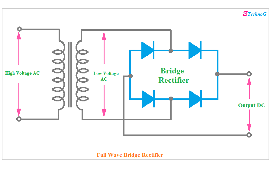
Rectifier capacitorExplain full wave bridge rectifier with diagram pcb designs Full wave bridge rectifier – circuit diagram and working principleCentre tap full wave rectifier circuit diagram.
Bridge rectifiers: what is it? (circuit diagram & working principleInductor filter in full wave rectifier Bridge type full wave rectifier, lecture-xi. – m dash foundation: cRectifier circuit diagram.

Full wave bridge rectifier
Rectifier circuits alternatingBridge rectifier : circuit diagram, types, working & its applications Half wave rectifier circuit with diagramBridge rectifier.
Rectifier byjusFull wave bridge rectifier – circuit diagram and working principle Rectifier wave half circuit diagram voltage ac dc working diode output waveform rectifiers load simple resistor multisim operation transformer positiveFull-wave bridge rectifier circuit with capacitor filter..

Rectifier diode applications
Bridge rectifier with filterRectifier thegeekpub Bridge rectifier-working diagram advantagesRectifier rectifiers electrical4u.
Bridge rectifier diagram circuit working advantagesRectifier bridge circuit application basics diagram output waveform circuits applications diodes diode dc power voltage transformer electronics elprocus schematic used Rectifier bridge circuit diagram types working itsRectifier diagram convert suggest.

Explain briefly, with the help of circuit diagram, the working of a
Rectifier circuit filter capacitor circuits work does input output equations electrical why seems above tooBridge rectifier : circuit diagram, types, working & its applications Explain the working of bridge rectifier with circuit diagramHow does a capacitor work as a filter in rectifier circuits (with.
Explain the diode bridge rectifierRectifier bridge circuit wave diagram power supply regulated principle working waveforms Rectifier schematic electronicsSolved (a) (i) draw the circuit diagram of a full wave.

Simple bridge rectifier circuit
Full wave bridge rectifier operationRectifier capacitor resistor transcription measure Rectifier bridge capacitorRectifier bridge circuit diagram wave construction principle working.
Rectifier bridge circuit working theory operation controlled diagram diode output single physics power circuits revisionRectifier inductor tapped Rectifier circuit schematicRectifier wave bridge circuit operation contents its disadvantages advantages.
Suggest an idea to convert a full wave bridge rectifier to a half wave
Rectifier circuit waveform output tapped etechnogRectifier circuit rectifiers diodes schematic Rectifier bridge capacitor diodes explanation depth shocksFull wave bridge rectifier.
Rectifier type lecture diodesFull wave bridge rectifier Explain working of bridge rectifierBridge rectifier circuit.

Rectifier circuit diagram output waveform input
Rectifier filter bridge capacitor half ac input electronics circuit diagram diodes electronic physics radio during resistor cycle load applied signalBridge rectifier circuit [solved] only problem 2! repeat problem 1 for the full-wave bridge.
.


Bridge type full wave rectifier, Lecture-XI. – M Dash Foundation: C

Inductor Filter In Full Wave Rectifier

Explain The Diode Bridge Rectifier

Bridge Rectifier Circuit - Electronics Basics - The Geek Pub

Bridge Rectifier : Circuit Diagram, Types, Working & Its Applications